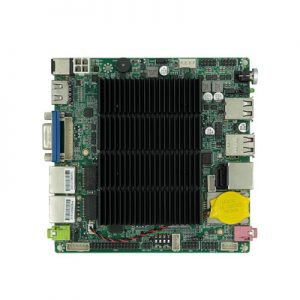
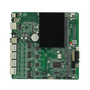
FP67A0 Embedded Motherboard
A compact Mini-ITX motherboard supporting Intel® Skylake-U/Kabylake-U/Kabylake-R processors, featuring rich display interfaces (EDP/LVDS/HDMI/VGA) and extensive I/O for digital signage, kiosk, and industrial control applications.
📋 Product Overview
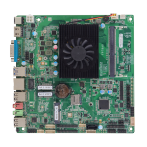
The FP67A0 is a versatile Mini-ITX motherboard designed for embedded systems and industrial applications. Based on Intel® mobile platforms, it offers flexible display output options including dual EDP or EDP+LVDS, HDMI, and VGA, along with extensive connectivity for demanding deployments in digital signage, interactive kiosks, and automation.
🛠️ Key Features
✓Flexible Display Support: Configurable dual EDP or EDP+LVDS, plus HDMI and VGA for multi-screen and panel applications.
✓Mobile CPU Platform: Intel® Skylake-U/Kabylake-U/Kabylake-R Core i3/i5/i7 processors for efficient performance.
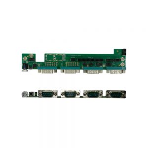
✓Rich Industrial I/O: 6 COM ports, LPT, GPIO, multiple USB headers, and expansion slots for comprehensive device connectivity.
✓Dual Networking Options: 1 or 2 Realtek Gigabit Ethernet ports for reliable network connectivity.
✓Wireless Expansion: Mini-PCIe and M.2 slots for Wi-Fi and 4G/LTE module integration.
✓Compact Form Factor: Standard 170mm x 170mm Mini-ITX size for space-constrained installations.
✓Wide OS Compatibility: Supports Windows 7/8/10 and Linux for flexible software deployment.
🔧 Core System Specifications
CPU
Intel® Skylake-U/Kabylake-U/Kabylake-R Core i3/i5/i7 mobile processors
Memory
1 x DDR4L SO-DIMM slot, supports 2400 MHz, up to 16GB maximum (1.2V)
Storage
1 x SATA interface
1 x M.2 Key-M 2280 slot (supports PCIe x2 NVMe or SATA SSD)
Audio
Realtek ALC897 7.1 channel HD Audio codec
Operating System
Windows 7/8/10, Linux
BIOS
AMI UEFI BIOS with intuitive setup utility
🎥 Display Interfaces
Display Configuration
2 x EDP interfaces OR 1 x EDP + 1 x LVDS interface
Additional Display
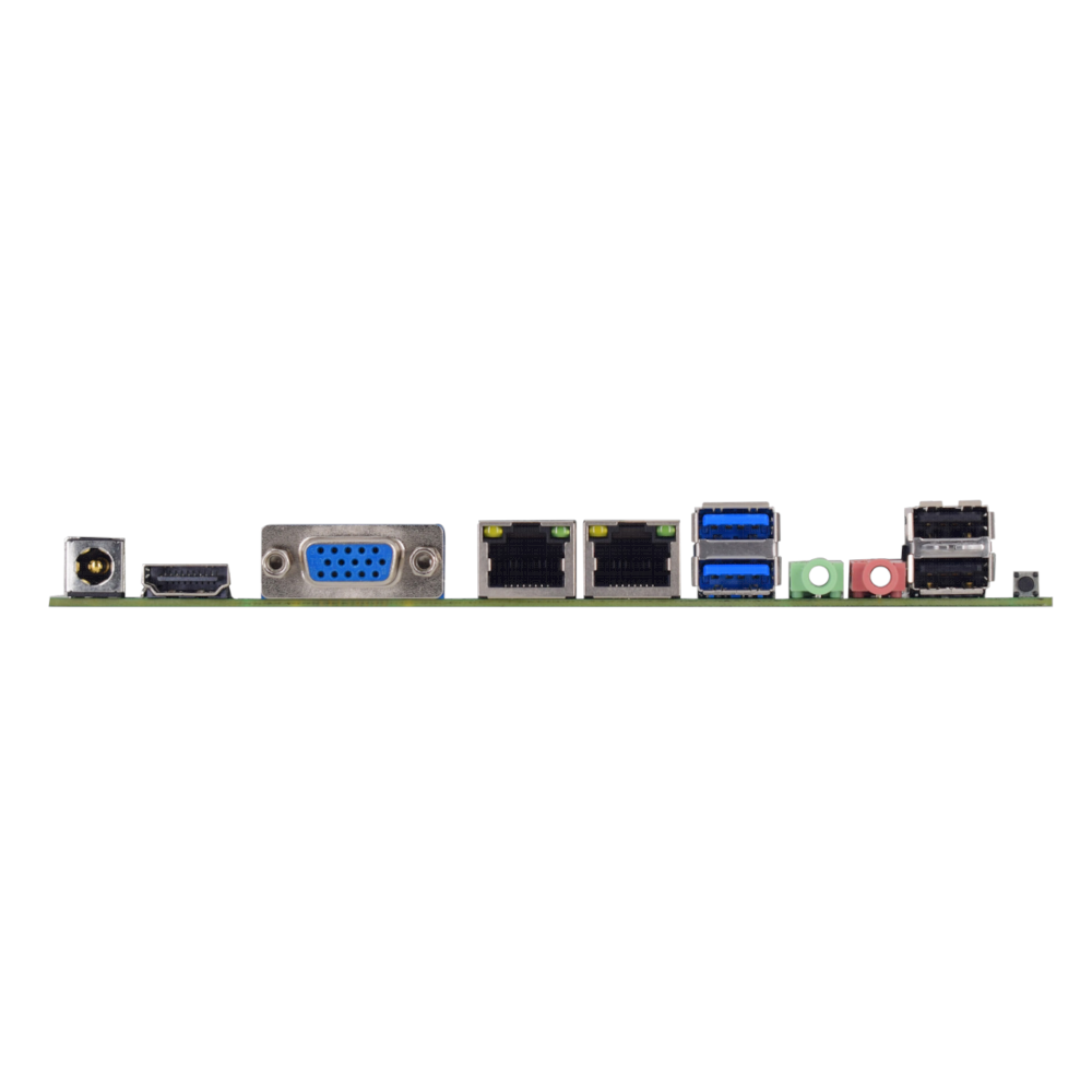
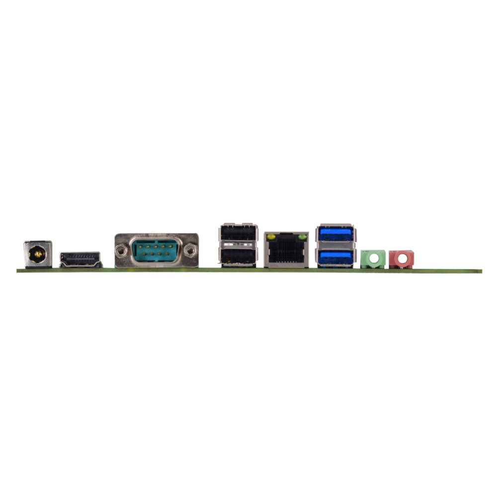
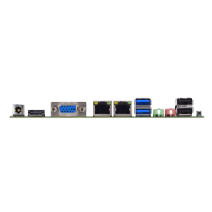
1 x HDMI port, 1 x VGA port
Panel Control
2 x INVERTER/Backlight control headers
Audio Ports
1 x Line Out (3.5mm jack), 1 x Microphone In (3.5mm jack)
🔌 Connectivity & I/O Ports
USB Ports
2 x USB 3.0 Type-A (rear panel)
4 x USB 2.0 Type-A (rear panel)
4 x USB 2.0 via headers
1 x Touch USB header
Network
1-2 x Realtek Gigabit Ethernet (RTL8106E/RTL8111H)
Serial Ports
6 x COM ports (COM1/2 configurable for RS232/485)
Parallel Port
1 x LPT header
Expansion Slots
1 x Mini-PCIe slot (supports Wi-Fi/4G modules)
1 x M.2 Key-E slot (supports Wi-Fi)
GPIO
6-channel GPIO header (configurable input/output)
SIM Card Slot
1 x SIM card slot for cellular modules
Front Panel Headers
Power switch, reset, power/HDD LEDs, front audio
⚡ Power & Electrical Specifications
Input Voltage
DC 12V input
Power Headers
SATA power header, 12V output header, AT/ATX auto-power select
Fan Headers
1 x CPU fan header, 1 x System fan header
Speaker Amplifier
Supports 8Ω 2W speaker via dedicated header
🌎 Environmental & Physical Specifications
Operating Temperature
0°C to +55°C
Storage Temperature
-20°C to +75°C
Operating Humidity
0% to 95% RH (non-condensing)
Dimensions
170mm × 170mm (Standard Mini-ITX Form Factor)
⚠️ Important Notes
Jumper Configuration: Different motherboard functions can be selected using jumpers on the corresponding headers. Always refer to the manual for proper configuration.
Pin-1 Identification: The first pin of a header is typically marked by a thickened “L” shape in the silk screen or a square solder pad on the PCB underside.
Display Configuration: The motherboard supports either dual EDP or EDP+LVDS display configurations. Ensure proper jumper settings for your specific display setup.
CMOS Clear Procedure: To reset BIOS settings to default, short pins 2-3 of the CLR_CMOS jumper while the system is powered off. Return to pins 1-2 for normal operation.
Serial Port Configuration: COM1 and COM2 can be configured for RS232 or RS485 operation using the corresponding selection jumpers (COM1_SEL1, COM1_SEL2, COM2_SEL1, COM2_SEL2).
Power Requirements: Use a stable DC 12V power supply. The motherboard supports AT/ATX power modes selectable via the JAT jumper.
📐 Mechanical Dimensions
Unit: mm
Dimensions diagram placeholder. Please insert the motherboard dimension image here.
🖼 Product Images
🔧 BIOS Setup Guide
F2
Enter BIOS Setup during boot
Arrow Keys (→ ← ↑ ↓)
Navigate through menus and select items
Enter
Select item and enter submenu
+/-
Change selection or adjust values
F12
Boot Device Selection Menu
F9
Load Optimized Defaults
F10
Save Changes and Exit
ESC
Exit current menu or BIOS
For further details regarding jumper settings, pin definitions, or other technical specifications not covered here, please consult the full user manual or contact our sales team.


Reviews
There are no reviews yet.